
Splitter & Adapter, Canbuau Ubuy Malaysia
Over 80% New & Buy It Now; This Is The New eBay. Find Ethernet Splitter Cable Now! Free Shipping Available On Many Items. Buy On eBay. Money Back Guarantee!
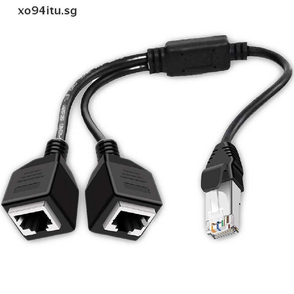
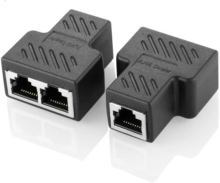
XOITU RJ45 Splitter Adapter 1 Male to 2 Female LAN Network Splitter Support Cat6
The Pros and Cons of Ethernet Cable Splitters. Cable Splitter Alternatives. Wireless Access Points. Powerline Ethernet. Network Switches. MoCA (Multimedia over CoAx) The Best Ethernet Splitters To Buy. RIOUSV Ethernet Splitter 2-Pack. Wuedozue RJ45 Network Splitter Adapter.
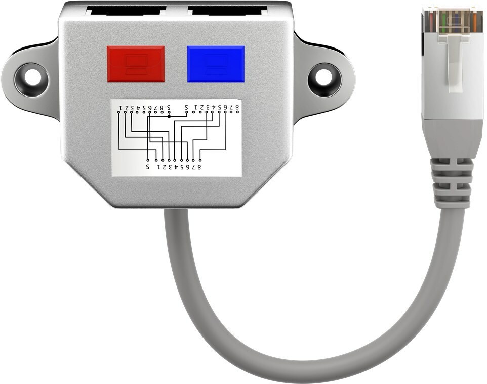
Goobay Splitter Pinout CAT 5 + ISDN Skroutz.gr
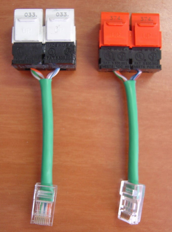
Step 3: Punch Down the Other End to the RJ-45 Keystone Jacks. Take the other end of the cable, cut it to 9 inches and punch down the four pairs using the following wiring scheme: Jack #1: 1 White/Orange to pin 1keystone jack. 2 Orange to pin 2 keystone jack. 3 White/Green to pin 3 keystone jack.

cable wall plate Gold Plated RJ45 CAT 7 LAN Splitter Connector Adapter PC 1 Pack
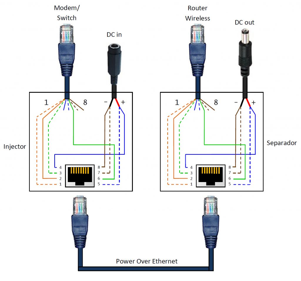
Here is a diagram to show you how a typical Ethernet splitter system works. Ethernet splitter wiring diagram. Basically, 100Mbps Ethernet only uses 2 out of the 4 pairs in a standard Ethernet cable unlike 1Gbps Ethernet which uses all 4 pairs. In 100Mbps Ethernet, 2 pairs simply get unused.

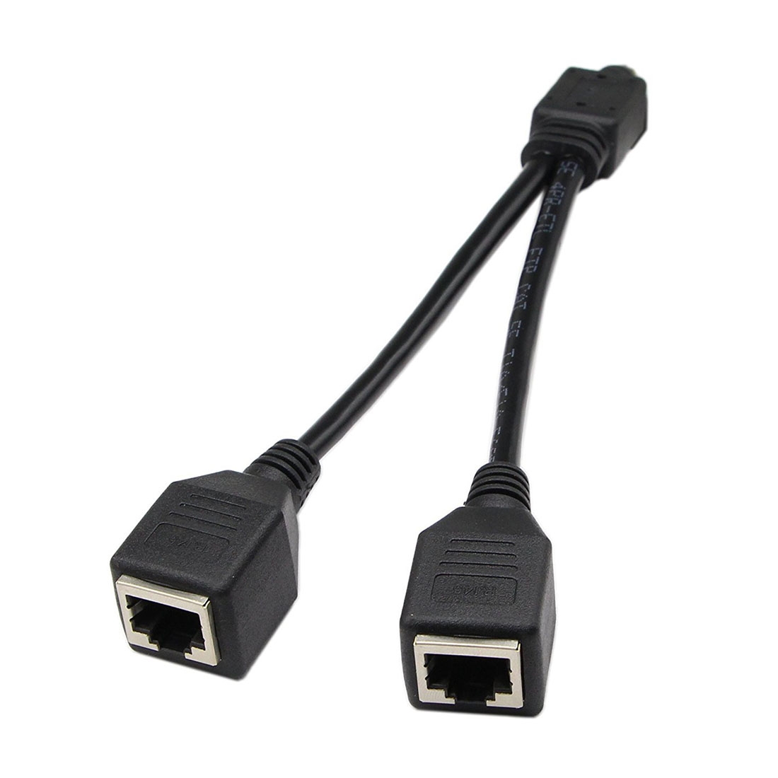
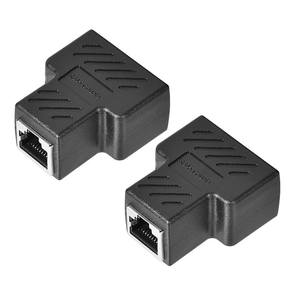
RJ45 Splitter, Splitter 1 to 2 Connector for RJ45 Cat5/Cat5e/Cat6/Cat7 Cable 2 Pack
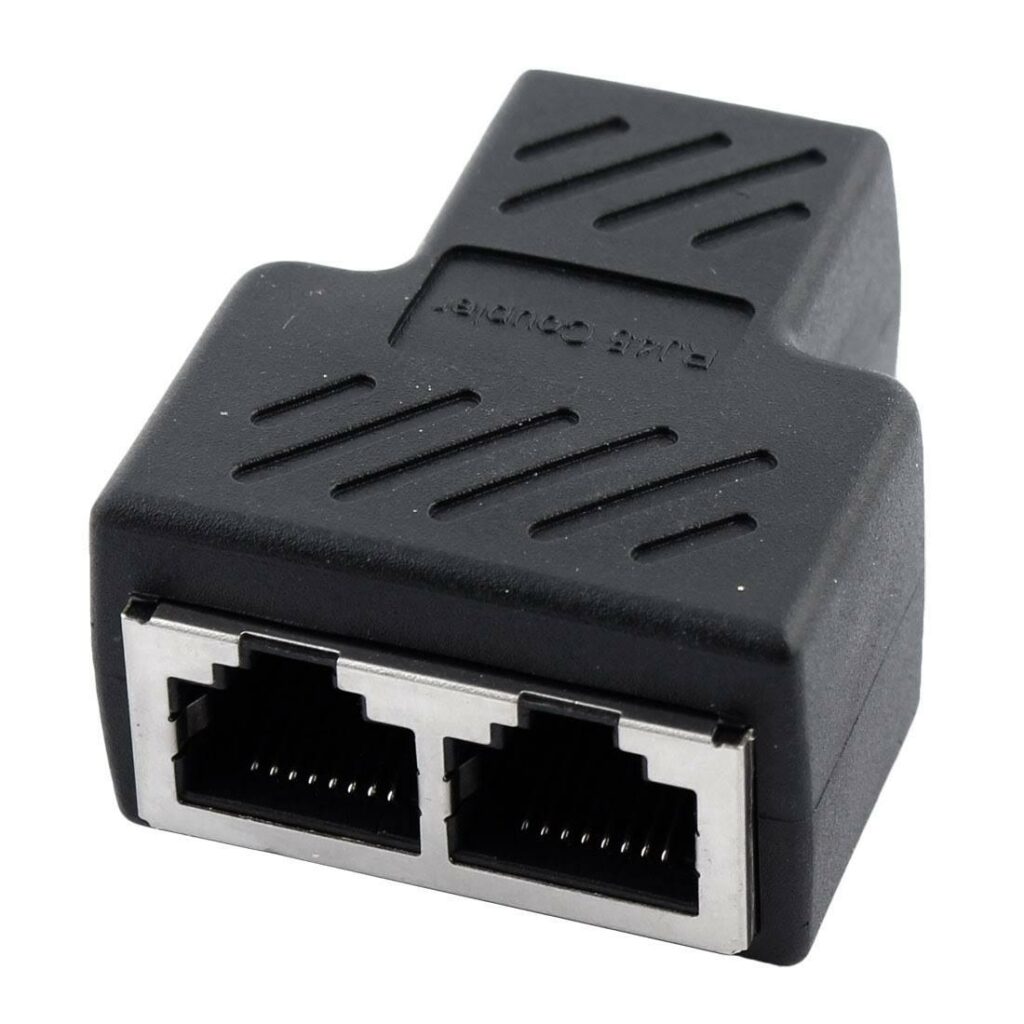
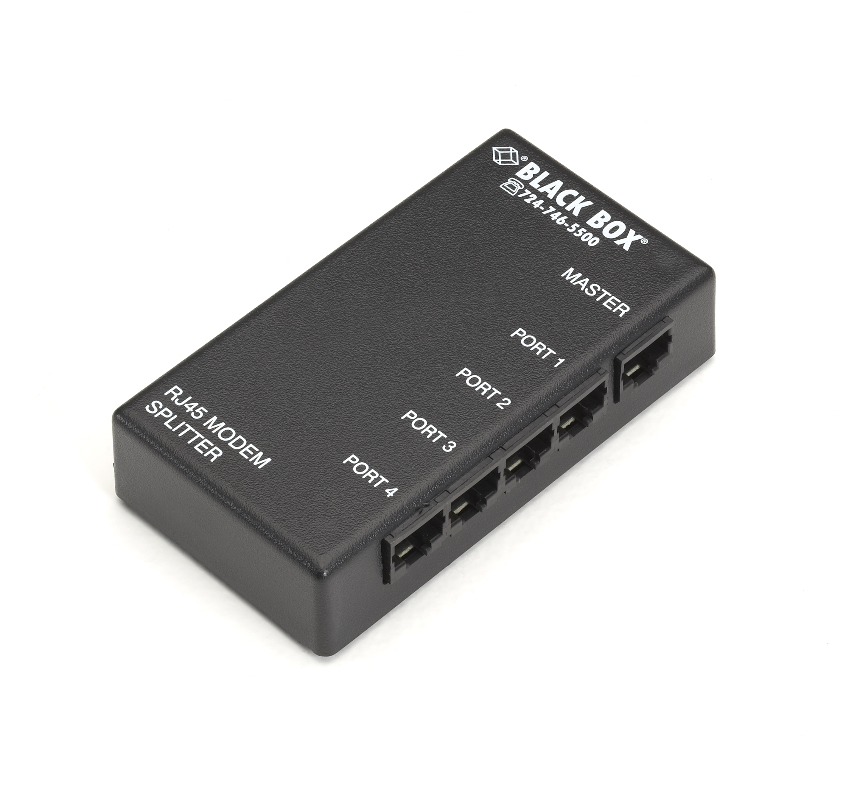
An Ethernet splitter is a simple device with three Ethernet ports on it. The idea is to allow you to run two Ethernet devices along a single cable without having to purchase and power a switch or run more cables. Splitters are incredibly cheap, but that's where the positives end. To use splitters, you'll need two: one to connect your two.
[DIAGRAM] Network Cat5 Spliter Wiring Diagrams
3) Connect another ethernet cable from the 1 port side of the splitter to the 1 port side of a 2nd splitter. (You may need to insert a female-female adapter to make this connection -- I have to). 4) Connect 1 ethernet cable from 2nd splitter 2-sided splitter port to 1 computer. 5) Connect another ethernet cable from the other 2nd splitter 2.
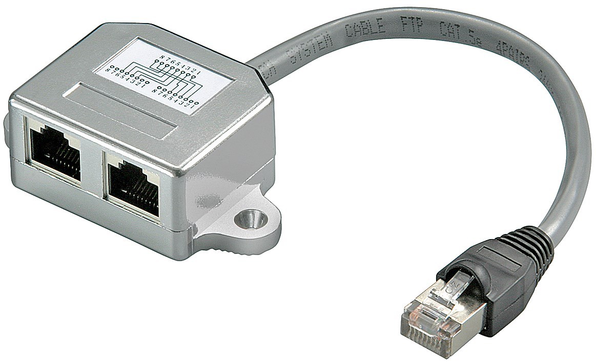
Cable splitter Pinout 2x ISDN; shielded(Yadapter) Elektronik Lavpris Aps
An ethernet splitter and parts provide electricity to devices connected by a network cable as a power source. It is highly adaptable, dependable, and simple to set up. This device separates power from data and sends it to a separate input. The splitter comes with two output wires. One wire transmits data, while the other delivers electricity.
Rj45 Splitter Wiring Diagram Wiring Diagram Wiring Diagram Rj45 Splitter Full Hd Spreadem
802.3at PoE+ splitter Schematic. The schematic is divided into 3 main parts: Top-left: ethernet transformer connections to ethernet cable IN terminals and ethernet OUT terminal; Top-right: termination of cable-side and device-side center taps (for more about this, see the previous post about building a passive gigabit PoE splitter)

Poe Pinout Diagram / Rj45 Schema Bei Ip Kameras X Security Visiotech Marcus Marks
Pinout of Power over Ethernet (POE) and layout of 8 pin RJ45 (8P8C) female connector and 8 pin RJ45 (8P8C) male connectorPower over Ethernet is a technology that allows IP telephones, wireless LAN Access Points, security network cameras and other IP-based terminals to receive power, in parallel to data, over the existing CAT-5 Ethernet infrastructure without the need to make any modifications.
Splitter What Is It & Does It Slow Down Connection?
The Ethernet Splitter Wiring Diagram is an essential tool for anyone who is looking to install or troubleshoot a wired ethernet setup. It provides a detailed visual overview of the physical connections needed to get the wired internet connection up and running quickly and correctly. When working with a wired connection, it's important to.
Poe Rj45 Pinout Diagram Wiring Diagram Poe Ip Camera Wiring Diagram Cadician's Blog
An Ethernet splitter wiring diagram provides a comprehensive look at how each component of the Ethernet splitter connects to each other. It will typically show the input port, output ports, power source, and any other connections needed for the device. It's important to note that the wiring diagram may vary depending on the model of Ethernet.

The Difference Between an Splitter, a Hub, and a Switch
Ethernet Cable Pinout Tech Faq. 802 3af At Standard Active Rj45 Port 10 100 1000mbps Mini Poe Gigabit Splitter China Power Over Ethernet Adapter Cable Injector Made In Com. Network Wiring Cable Computer And Examples Layout Floor Plans How To Use House Electrical Plan Software Cabling Diagram. Rj45 Male To Terminal Adaptor 485 Rs232 Rs458.
RJ45 Splitter Coupler Inline Connector 1 To 2 Splitter Cat7 Cat6 Cat5e Cable Extender
An Ethernet Splitter Wiring Diagram is a visual representation of how the different components that make up an Ethernet connection are connected. It indicates the type of cables used, the ports to which they are connected, and the pinouts for each port. This diagram is a great tool for both professional and home users to easily set up a.
Splitter What it Does, Which Type to Buy, Alternatives
Pinout of Ethernet 10 / 100 / 1000 Mbit (cat 5, cat 5e and cat 6) network cable wiringNowdays ethernet is a most common networking standard for LAN (local area network) communication. The ethernet cable used to wire a RJ45 connector of network interface card to a hub, switch or network outlet. The cable is called wipe, patch cord, straight-thru cable.

How to use a splitter. LMN technohub
An ethernet splitter allows you to divide a single incoming Ethernet connection into multiple connections. On the other hand, an ethernet switch allows you to expand the number of ports available on your network. It connects multiple devices and directs data to the correct device using packet-switching technology.
Unbedeutend bevorzugt Schuldig splitter box Doppelschicht Gefühl Marco Polo
Step 3: Punch Down the Other End to the RJ-45 Keystone Jacks. Take the other end of the cable, cut it to 9 inches and punch down the four pairs using the following wiring scheme: Jack #1: White/Orange to pin 1keystone jack. Orange to pin 2 keystone jack. White/Green to pin 3 keystone jack.